
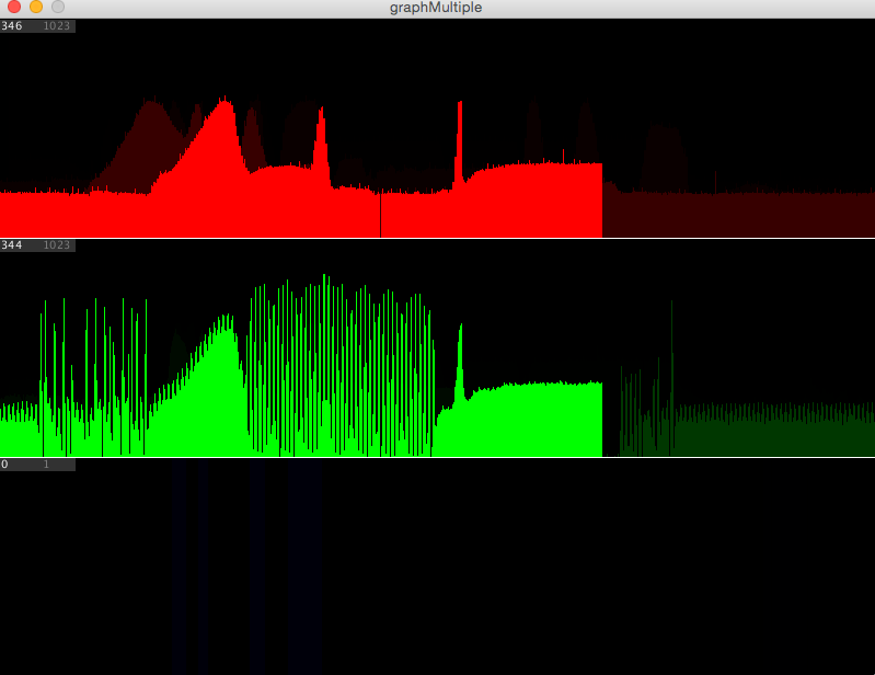
Here is my version of the Graph example code that simplifies things for easier adaptation, plus some other cool stuff like a translucent overlay to see past data history. It’s designed to use any number of sensors or other data, analog or digital, binary or 8-bit or 10-bit or whatever you want, with generic variable names that you can change to suit.
Note the 20mS delay between sending serial data packets. This is because the Arduino sends data faster than Processing can read and act on it. If you need a faster more synchronized response, use the Call & Response method instead.
NOTE: until code formatting is improved, immediately after you paste code, use the Auto Format command (in the Edit menu), this will clean up and correct indentation…
ARDUINO CODE:
/*
Send COMMA- or TAB- SEPARATED ASCII-encoded strings to serial port.
(Commas/tabs are also helpful to read numbers when you are debugging)
Values 0-1023 or even higher can be sent, followed by a newline, or newline and carriage return
Output can be viewed in Arduino Serial Monitor, *or* Processing with code below

Created 30 Apr 2012, Modified August 2015
by Eric Forman
(based on Virtual Color Mixer and Graph examples by Tom Igoe)
*/

// rename these for your sensors:
int Apin = A0;    // analog
int Bpin = A1;    // analog
int Cpin = 2;     // digital pin
int A, B, C;

void setup()
{
  Serial.begin(9600);
  pinMode(Cpin, INPUT);
}

void loop()
{
  A = analogRead(Apin);       // 0-1023 (in theory)
  B = analogRead(Bpin);       // 0-1023 (in theory)
  C = digitalRead(Cpin);      // 0-1

  Serial.print(A);
  Serial.print(",");
  Serial.print(B);
  Serial.print(",");
  Serial.println(C);

  delay(20);                  // slight delay to slow down data flow
}
PROCESSING CODE:

Instead of receive multiple inputs in computer using processing code, how we can receive multiple inputs simultaneously with arduino through serial communication. I’m trying to communicate serially between two arduinos using multiple inputs.
Please let me know!
Blessings!
LikeLike
Marcos, try using i2c. A good explanation with example code is here.
LikeLike
Thanks for reply the message, but the problem is that I need to make the communication via TX / RX pins. This is because I will use an rs485 shield to transmit long distance. Rs485 sustain transmission in long distance. This shield use TX / RX pins to establish the communication between arduinos.
Let me know!
Blessings!
M. Soto Cora, PE, ME
LikeLike
im using it with and AXDL345 sensor and works just perfect
thank you!
LikeLike
I would like to plot the real time graph from input provided by the arduino (IMU sensor). I wish to see the axes and adaptive axes for the processing code. Help me out with the processing code. The below is my arduino code.
Arduino code:
#include#include
/*
x_IMU_Arduino_Example.ino
Author: Seb Madgwick
Example usage of x-IMU C++ library. Also uses the quaternion library to
convert the received quaternion to Euler angles.
Requires two hardware serial modules: one to receive from the x-IMU and one
to transmit the decoded data to be displayed on computer.
x-IMU settings:
Auxiliary Port > Auxiliary Port Mode: "UART"
Auxiliary Port > UART > Baud Rate: 115200
Auxiliary Port > UART > Hardware Flow Control: Off
Hardware connections:
x-IMU GND -> Arduino MEGA GND
x-IMU EXT -> Arduino MEGA 5V
x-IMU AX2 -> Arduino MEGA RX1
Tested with "arduino-1.0.3" and "Arduino MEGA".
//------------------------------------------------------------------------------
// Variables
XimuReceiver ximuReceiver;
//------------------------------------------------------------------------------
// Functions
void setup() {
Serial.begin(115200); // for sending data to computer
Serial1.begin(115200); // for receiving data from x-IMU
}
void loop() {
ErrorCode e = ERR_NO_ERROR;
// Process recieved data
while(Serial1.available() > 0) {
e = ximuReceiver.processNewChar(Serial1.read());
}
// Print error code (receive error)
if(e != ERR_NO_ERROR) {
Serial.print("ERROR: ");
Serial.print(e);
Serial.print("r");
}
// Print quaternion data as Euler angles
if(ximuReceiver.isQuaternionGetReady()) {
QuaternionStruct quaternionStruct = ximuReceiver.getQuaternion();
Quaternion quaternion = Quaternion(quaternionStruct.w, quaternionStruct.x, quaternionStruct.y, quaternionStruct.z);
EulerAnglesStruct eulerAnglesStruct = quaternion.getEulerAngles();
Serial.print("roll = "); // roll,pitch and yaw respectively
Serial.print(eulerAnglesStruct.roll);
Serial.print(", ");
Serial.print(eulerAnglesStruct.pitch);
Serial.print(", ");
Serial.print(eulerAnglesStruct.yaw);
Serial.print("n");
}
}
Help with processing code which has my variables.
LikeLike
There is a new approach in science for sampling an unlimited number of sensors in parallel, called photon-pixel coupling.
LikeLike
Cool. Is that useful for these relatively low resolution analog sensors and Arduinos?
LikeLike
Yes, because resolution is relevant with photon-pixel coupling, that is the beauty of it. You can read one pixel per sensor. So, the maximum number of sensors sampled in parallel is directly proportional with the cam resolution.
At 640x480p you can sample a maximum of 307200 sensors in parallel at 60Hz (60fps). That is a lot, it is huge !
At other higher resolutions of the cam … the number of sensors that can be sampled in parallel goes to millions (but it will work only for PCs in my opinion because it has the processing power. With arduino, I expect that we can sample at least a couple of hundred sensors easy.
LikeLike